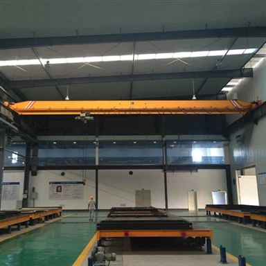


15 Ton Single Girder Overhead Crane Sold To Ghana
Nov 11, 2026
15 ton Single Girder Overhead Crane Specifications
|
Item |
15 ton single girder overhead crane |
|
Span |
22 meters |
|
Lifting Height |
11 meters |
|
Lift Speed |
0.6-4 m/min(with VFD) |
|
Trolley Speed |
2-20 m/min(with VFD) |
|
Long Travel Speed |
3-30 m/min(with VFD) |
|
Power Supply |
380V 50HZ 3P |
|
Lifting Power |
16 kw |
|
Cross Travel Power |
0.96 kw*2 |
|
Working Class |
M5 |
|
Operating Temperature |
-40℃ ~ +50℃ |
|
Electrics Brand |
|
|
Material |
Q355E |
|
Insulation Class |
H Class |
|
Electric Protection Class |
IP55 |
Parameter Interpretation: Why This Configuration Suits the Duty
The 13 mm wire rope is the load-bearing heart of the CD hoist. For a 15 t rating, this diameter provides a healthy safety margin and is a standard size with widely available replacement ropes-an important consideration for a site where spare-part logistics may extend lead times. The IP44 protection class is appropriate for a general workshop: it excludes solid objects larger than 1 mm and splashing water from all directions, which covers the dust and occasional washdown conditions typical of maintenance bays. The −40°C to +50°C operating range is broader than Ghana's ambient temperatures require, but this is a virtue rather than a redundancy: it means the crane is not operating near its thermal limits, and derating due to heat is not a concern
The combination of pendant cable control and wireless remote is a practical safety and productivity feature. The pendant provides a direct, hard-wired control path that is independent of radio frequency conditions-essential in a workshop with welding arcs, variable-frequency drives, or other sources of electrical noise. The wireless remote frees the operator from the pendant's radius, allowing a better view of the load and the ability to stand clear of the lift path. International practice for wireless crane controls emphasises that emergency-stop capability must be maintained even under signal loss, and that the remote must incorporate error checking to prevent response to corrupt data. In a well-specified unit, these are design requirements rather than optional features; the dual-control arrangement ensures that if the wireless link is compromised, the pendant remains available.
Installation and Load Testing Sequence
The installation requires a continuous progression from no-load through static and dynamic load testing.
Pre-installation verification:
Before erection, the runway beams were checked for span, elevation, and straightness. As-built runway tolerance is the single most common reason a new crane exhibits flange wear, skewing, or uneven long-travel motor loading within its first two years; a crane that is well built but installed on an out-of-tolerance runway will underperform its design life. The 22 m span was confirmed against the actual runway gauge, and the rail top surfaces were verified for level within the specified tolerance.
Erection and alignment:
The crane was assembled using a mobile crane of adequate capacity. The end carriages were set onto the rails, the main girder was lowered and bolted to the end carriage connections, and the CD hoist trolley was introduced onto the bottom flange of the girder. The wire rope reeving was completed with attention to the requirement that the rope must not twist, kink, or contact the hoist housing during entry and exit from the guide device; at the lower limit position, a minimum of two dead wraps must remain on the drum, excluding the fixing turns. The 13 mm rope was inspected for broken wires, and the hook block was checked for free rotation and secure latch operation.
No-load, static, and dynamic testing:
The no-load test verified all motions-hoist up/down, cross-travel, and long-travel-without abnormal noise, vibration, or binding. The static test applied 125% of the rated capacity with the trolley at mid-span, the load suspended approximately 100 mm above the floor for 10 minutes. Three consecutive static tests were performed, and after the third unloading, the main girder was inspected for residual deformation; none was found. The dynamic test followed at 110% of rated capacity, exercising repeated hoisting, lowering, and braking, together with cross-travel and long-travel runs across the full span. Brake response, limit switch function, and control reliability were verified during this phase. The dual-control system was tested in both pendant and wireless modes, with the emergency-stop function confirmed in each.
Conclusion
The 15 ton single girder crane delivered to the Ghanaian workshop is a case of equipment matched to context. The 11.15 m span addresses the actual bay width rather than a catalogue dimension; the A3 classification reflects the intermittent maintenance duty that ordinary workshops impose; the 6.5 kW total power is sized for a shared industrial supply; and the pendant-plus-wireless control arrangement provides both hard-wired reliability and operational flexibility. The successful installation and load testing confirm that the crane is ready for service. Its long-term performance will depend less on the equipment itself than on disciplined inspection of the rope and brake, and on operating within the A3 duty envelope for which it was designed.
If you have lifting requirements for such equipment, please feel free to contact us. We provide professional operational analysis, customized design solutions, and high-quality products that have undergone rigorous inspection.