Crane Overload Protection Device
May 20, 2023
Crane Overload Protection Device
Crane overload operation is one of the main causes of crane accidents. The use of sensitive and reliable overload protection devices is an effective measure to improve the safety of crane operations and prevent overload accidents.
The crane overload protection device includes a lifting capacity limiter and a lifting moment limiter.
The setting of the action point of the crane overload protection device should consider three aspects: general requirements, dynamic load conditions, and special load conditions, which are listed below.
(1) General requirements
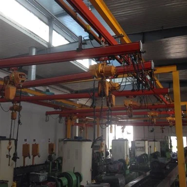
The action point of the overload protection device refers to the actual lifting capacity of the 15 ton overhead crane when the crane stops moving in an unsafe direction due to the overload protection function of the device under the installed condition. The usual action point setting should consider three factors:
① The crane should be able to lift the rated load without reducing the original lifting capacity.
② It should not exceed its dynamic load test value <110% of rated lifting capacity>.
③ The comprehensive error of ±5% of the overload protection device should be considered. It is generally set within the range of 100%~105% of the rated lifting capacity.

(2) Consider the dynamic load situation
During the normal operation of the 15 ton overhead crane, when the object is suddenly lifted off the ground or lowered and braked, an additional dynamic load will be exerted on the bearing structure. This load effect can be considered by multiplying the lifting load by the dynamic load factor of the lifting load & greater than 1.
It can be seen that the setting of the action point of the overload protection device must consider the fact that there is a dynamic load in the normal operation of the crane to avoid misoperation.
Our current overload protection device adopts the method of "delayed power-off" in the setting of the action point to solve this problem. Delayed power-off means that when the load signal reaches the set action point load signal, the device will act after being judged by the delay link, stop the crane from running in an unsafe direction, but allow it to run in a safe direction.
The delay link is generally processed by a circuit, or a single-chip microcomputer through software, and the delay time is determined according to the vibration of the crane structure.
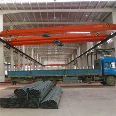
For a 20 ton bridge crane, when the rated load acts on the mid-span of the main girder, the full-load natural vibration frequency (wire rope pulley block) in the vertical direction is 2Hz≤f<4Hz.
For jib cranes, such as gantry cranes, when the rated load acts on the maximum amplitude, the full-load natural vibration frequency is f≥1Hz. Therefore, the delay time is generally taken as 1-2s to avoid large vibration loads.
According to theory and actual testing, when the load lifted by the crane is critical to the set value of the action point, the device realizes the function of delayed power failure. However, because the vibration cannot be completely eliminated, or due to factors such as heavy objects shaking left and right and signal interference, the load signal may be lower than the set value of the action point, causing the relay contact to release, resulting in multiple delayed power outages.
The multiple actions of the relay contacts will cause the motor of the crane mechanism to start and stop at times, which will have adverse vibration effects on the structure and increase unsafe factors on the contrary. Therefore, when designing the product, the device should be locked once after a delayed power failure. When the load signal drops to a certain signal value (preferably below 90% of the rated lifting capacity), the normal operation of the various mechanisms of the crane can be resumed.
For the lifting capacity limiter, the crane generally lowers the item to the ground; for the lifting moment limiter, the crane generally adopts the method of reducing the amplitude.

(3) Consider special load conditions
There are the following special situations in the actual operation of the crane:
In the case of misoperation, the crane driver suddenly puts the control handle in the highest speed gear, and the hook has reached a very high speed before the lifting wire rope is loaded. Lifting objects at this speed will cause great shock and vibration load;
During the hoisting operation of the crane, the objects being lifted may collide with other obstacles, or the objects may be consolidated with the ground, resulting in a sudden increase in load and causing great damage to the crane.
In the above two cases, it is obviously impossible to achieve the protective effect only by using the delayed power-off method, so the product must be set with another action point, which is the "peak power-off" method usually used in product design.
Peak power cut-off means that when the load signal reaches a certain set peak load signal, whether it is a dynamic load signal or an actual load signal, the device can act immediately without delay to stop the crane from running in an unsafe direction, but allow the crane to move in a safe direction. run.
To correctly set the peak operating point of the device, it is necessary to consider the type of crane, the dynamic load coefficient, the strength of the structure and parts, the stability of the whole machine and the load combination of the crane in actual work, and make a reasonable choice.